
Preparing Files for Construction 3D Printing: From Model to Toolpath
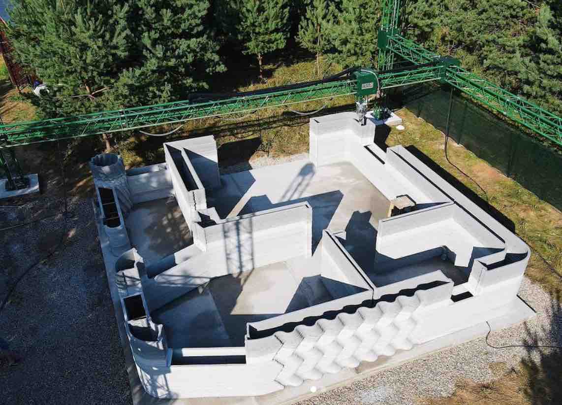
A construction 3D printer does not print directly from an architectural rendering or an unverified building model. The geometry must be reviewed, divided into printable operations, converted into controlled toolpaths, and coordinated with the selected printer, material-delivery system, layer dimensions, and construction sequence.
AMTG manufactures construction 3D printing equipment and supports equipment owners with file review and print preparation. The customer’s architects, engineers, material specialists, and construction professionals remain responsible for the approved design, structural calculations, reinforcement, permits, site execution, and code compliance.
What a printer-ready construction file must address
A printable model must describe more than the visible shape of a wall. It must account for the selected machine’s working envelope, nozzle and layer geometry, material behavior, travel paths, start and stop points, openings, reinforcement strategy, construction joints, and access for conventional building operations.
- Geometry that can be reached by the selected printer configuration
- Continuous and stable extrusion paths
- Layer height and bead width appropriate for the qualified material
- Openings, corners, curves, transitions, and planned construction joints
- Space for reinforcement, utilities, insulation, and wall-cavity filling
- A printing sequence coordinated with site logistics and material supply
From digital model to machine toolpath
1. Define the application and printing envelope
The process begins with the intended structure or component, its maximum dimensions, the printing location, and the required production sequence. These parameters help determine whether a mobile robotic system, a large-format gantry printer, or a factory platform is the appropriate starting point.
2. Review and simplify the geometry
The source model is checked for discontinuities, inaccessible areas, unnecessary detail, problematic transitions, and geometry that conflicts with the physical printing process. Printable wall shells and component paths are then organized around the intended layer strategy.
3. Establish layer and extrusion parameters
Layer height, bead width, path spacing, travel speed, material output, and setting behavior must work as one system. These parameters are application-dependent and must be validated with the selected printable mixture and equipment configuration.
4. Generate and review toolpaths
The geometry is converted into an ordered sequence of machine movements. The review should identify start and stop locations, non-printing moves, direction changes, potential collisions, interruptions, and areas where the material-delivery rate must be coordinated with printer motion.
5. Validate before production
Dry runs, representative test sections, and material trials help confirm machine reach, extrusion continuity, dimensional accuracy, layer stability, and the planned operating sequence before full production begins. Approved files and parameter sets should be version-controlled so the operating team uses the correct release.
How AMTG supports equipment owners
AMTG can assist customers with evaluating the intended application, selecting a suitable printer configuration, reviewing geometry for the printing process, and preparing files for operation on AMTG equipment. This support is coordinated with the printer, synchronized mixer and pump, power generator, material workflow, and—where included—the foam-concrete production unit used to prepare infill for cavities between printed wall shells.
AMTG also provides guidance based on construction-printing mixture recipes with different setting times, colors, aggregate fractions, and plasticity, and can recommend suitable ready-made commercial mixtures. Final material qualification and project-specific engineering must be completed by the customer’s responsible professionals and material suppliers.
Information to provide for a file review
- General project description and intended printed elements
- Maximum dimensions and planned printing location
- Available architectural or fabrication model
- Required openings, reinforcement, utilities, and wall composition
- Preferred printable material or locally available material options
- Target production sequence and schedule
- Site access, utilities, and environmental constraints
To select the appropriate platform, compare AMTG construction 3D printers. You can also review the complete equipment package and support or send your project information to AMTG for the next technical and commercial steps.